Our approach to Passivhaus: Structure & Performance
Approx 8 min read
PART 2
Structure and Performance - Why Passivhaus Bans Assumptions
In a certified Passivhaus, performance isn’t a hope or best practice, it’s a measured outcome. Structural choices affect thermal bridges, moisture paths and comfort as much as insulation and ventilation. This post explains how and why.
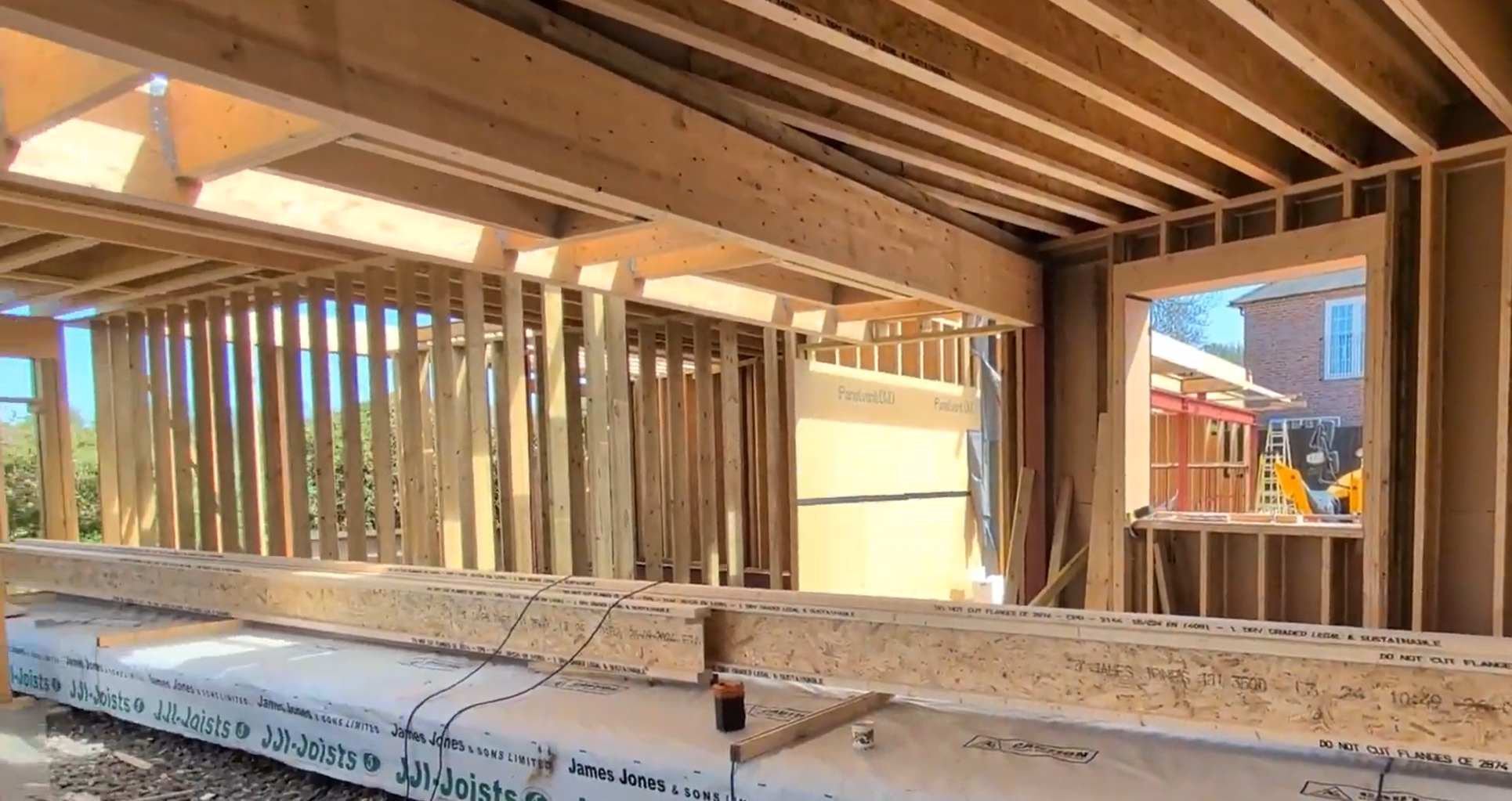
James Jones I-beam and glulam build construction in progress
I-Beams vs. Conventional Stick Framing
In Part 1, we talked about how the right foundations lay the groundwork for a high-performance building. Now, we’re moving up into the structure and particularly how our framing choices impact thermal performance and overall building health.
At this stage, we’re comparing traditional stick framing with the use of engineered timber I-beams. Not just from a structural perspective, but in terms of how each system behaves thermally and how that fits within a fully modelled Passivhaus approach.
Conventional Stick Framing - Built on Assumptions
Traditional stick-framed walls, typically using 2x6 or 2x8 timber studs, are still widely used in domestic construction. Structurally, they do the job. But thermally, they’re a compromise. Every solid timber stud in that wall is a thermal bridge. Insulation sits between them, but each stud creates a direct path for heat to escape and a consistent pathway for cold to enter.
That solid piece of timber becomes a kind of thermal expressway, and in many builds, this goes unaccounted for.
In conventional builds, thermal bridging should be measured, but often isn't due to not being a pre-requisite under building regulations. Energy Performance Certificates (EPCs), for example, base their energy ratings on default values and generic inputs. These assume consistent performance across all materials, regardless of junctions, transitions, or changes in material type.
In reality, those changes are everywhere and every material behaves differently when it comes to heat, moisture, and air movement. Without accurate modelling, you’re left with guesswork and often this is what results in the performance gap
Modelling Matters
With Passivhaus, all of the structure and cold bridging is fully modelled. Every junction, every layer, every structural element is calculated, not assumed. This is one of the most powerful aspects of Passivhaus: it removes all assumptions and gives you a prescribed, evidence-based performance outcome.
There’s still flexibility, there are always choices to be made in terms of detailing, materials, and structure, but nothing is hidden. Every compromise or gain is visible in the model so you know what you’re working with and more importantly, where potential issues are likely to occur.
Worked example: Window lintel load paths in timber frame construction
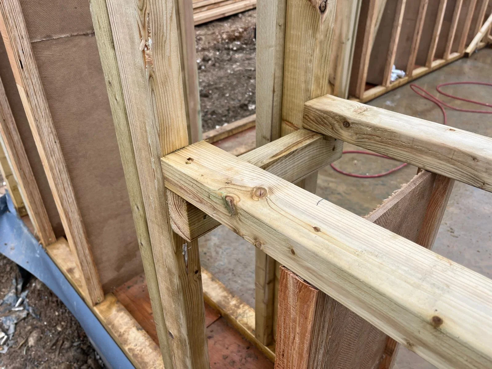
Site photograph of a typical OSOTIMBER window sill detail in an I-beam wall construction, demonstrating how the load-bearing structure is kept to the internal face to minimise thermal bridging and optimise the insulation zone.
At window openings, structural requirements and thermal performance often come into conflict.
The way loads are carried through the wall directly influences how many solid elements cross the insulation zone, and therefore how much thermal bridging needs to be accounted for in the model.
The diagrams below illustrate two different approaches to organising structure around a typical window lintel: a timber I-beam wall with a rationalised structural layout, and a conventional stick-frame wall with a distributed load path.
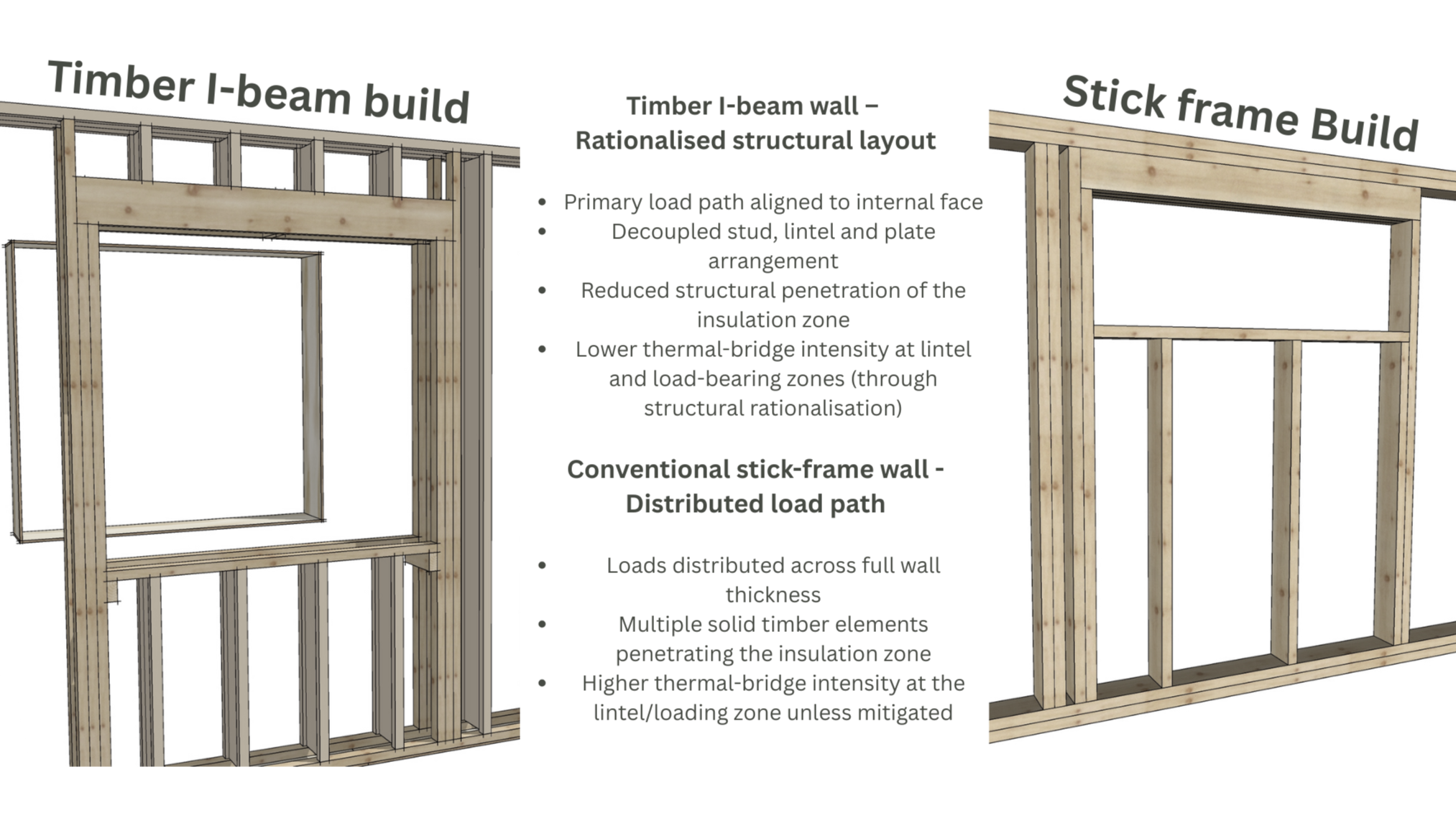
Figure X - Window lintel junction showing structural load path and thermal-bridge intensity
In timber I-beam construction, primary structural loads are deliberately aligned to the internal face of the wall.
This reduces the number and extent of solid timber elements penetrating the insulation zone, lowering thermal-bridge intensity at critical junctions such as lintels and load-bearing zones.
In conventional stick-frame construction, loads are typically distributed across the full wall thickness.
This increases the amount of solid timber crossing the insulation zone and makes thermal performance at junctions more sensitive to assumptions unless explicitly modelled and mitigated.
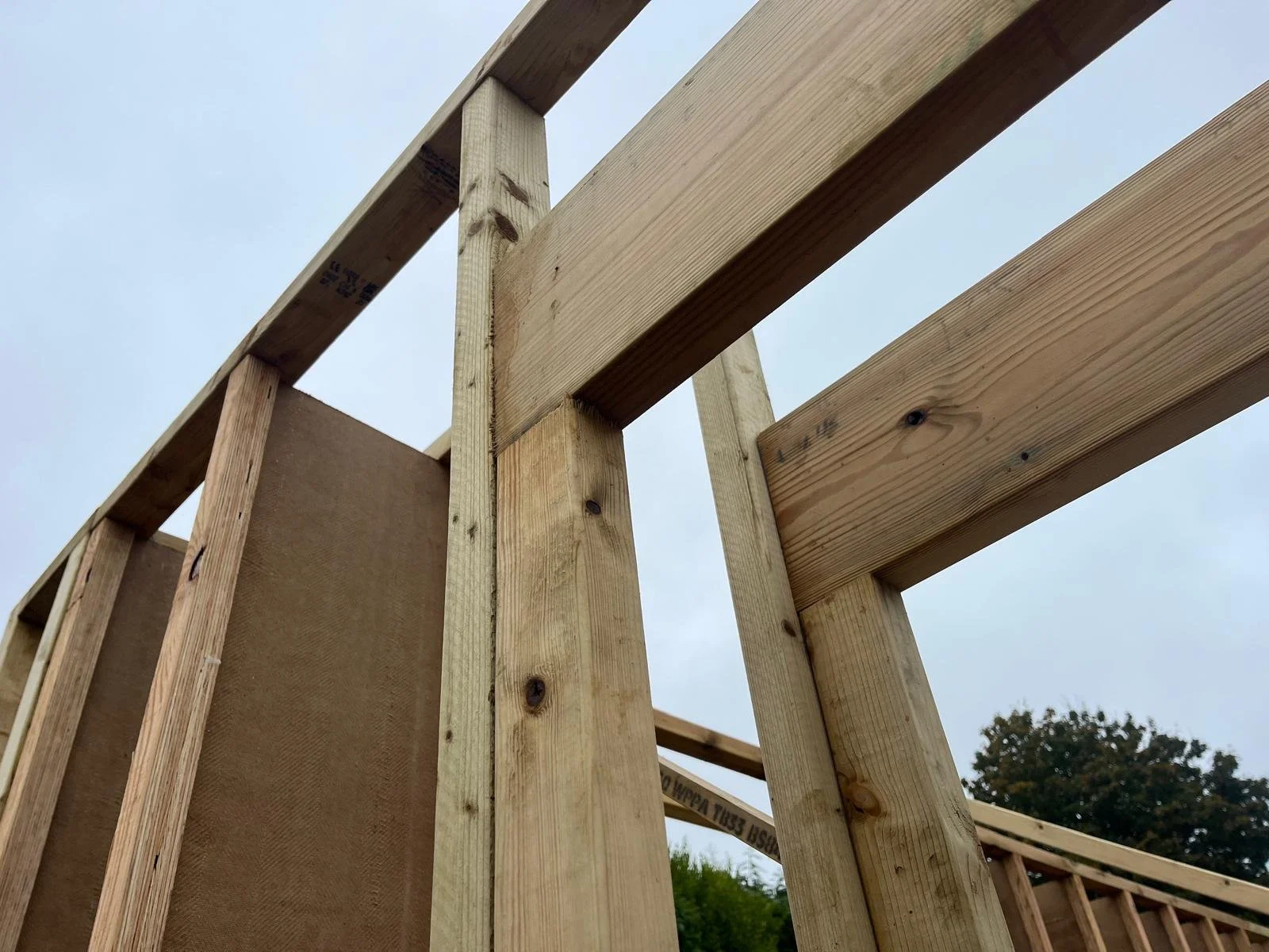
Site photograph of a typical OSOTIMBER window lintel detail in an I-beam wall construction, demonstrating how the load-bearing structure is kept to the internal face to minimise thermal bridging and optimise the insulation zone.
Cold Bridges and Dew Point
One of the biggest risks with cold bridging is what happens at the dew point, where warm air inside the building meets a cold surface within the structure, leading to condensation. In winter, the inside is warm and the outside is cold, in summer, this reverses. But in both cases, if the dew point lands within your structural layer and particularly on an uninsulated or poorly modelled element, you’ve got a long-term moisture problem.
We regularly see buildings that are well-insulated in theory but riddled with unmodelled cold bridges that cause real problems: heat loss, condensation, damp patches and mould.
The Rule of Thirds
That’s why Passivhaus introduces a general rule of thirds when it comes to structure and insulation.
Structural elements can pass into the insulation layer by up to one-third of its thickness without requiring detailed modelling. However, when they extend beyond this point, they must be modelled to assess the impact on thermal performance and determine whether compensatory measures are needed.
In some cases, it’s not possible to eliminate thermal bridges entirely but that’s where early involvement of a Passivhaus designer, such as OSOTIMBER, can make all the difference. By working closely with the design team from the outset, we can identify potential cold-bridge issues early and either design them out or develop tailored solutions. Sometimes it’s about simplifying the structure; other times it’s about creative problem-solving and we’re well equipped to do both.
This isn’t just theory. We’ve seen how even a few poorly detailed cold bridges can cause catastrophic failures especially when they’re embedded in bio-based wall systems. If you’ve got timber or natural insulation sitting next to a cold steel element or concrete bridge, and it’s sitting at or near the dew point, the structure starts to sweat. Once moisture builds up, it becomes the perfect environment for mould, rot, and long-term fabric degradation.
These are the kinds of issues that happen when structures are designed around strength and/or aesthetics alone, without properly modelling thermal performance.
Timber vs. Steel or Concrete
Timber naturally performs better than steel or concrete when it comes to thermal performance. Steel is highly conductive and will absorb heat or cold rapidly, pulling it into the building or letting it escape. Timber is inherently more insulative, which makes it a much better fit for high-performance wall systems. That said, even with timber, the way it’s used makes all the difference.
Solid Timber Studs vs. I-Beams
| Feature | Solid Studs (Stick Frame) | I-Beams (Engineered Timber Studs) |
|---|---|---|
| Material Span | Full 45×140 mm timber section runs continuously through the wall. | Only the 9 mm web spans the insulation layer between the flanges. |
| Thermal Bridging | Acts as a full thermal bridge from inside to outside, increasing heat loss. | Significantly reduced thermal bridge due to the narrow web. |
| Condensation Risk | Higher risk – dew point often falls within the solid timber, especially without external insulation. | Lower risk – thinner web keeps dew point more predictable and reduces cold surface areas. |
| Insulation Depth | Limited by stud thickness – achieving high insulation levels requires very thick walls. | Allows greater insulation depth within the same overall wall thickness. |
| Suitability Without External Insulation | Can perform adequately but may require careful detailing or internal solutions to manage cold bridging. | Performs better thermally on its own, but may still benefit from external insulation for optimum performance. |
| Best Use | Simple, familiar construction – works best where external insulation or thermal breaks are added. | Efficient for energy performance – ideal when aiming to minimise cold bridging within a slim wall profile. |
Potential Challenges with Solid Timber Studs
When building with standard solid timber studs, the whole section of timber runs through the wall, directly connecting the interior and exterior layers. It becomes a true thermal bridge, allowing cold to travel inside and warmth to escape.
Some builders try to fix this with thicker walls or continuous insulation outside the frame. But unless you model what’s happening inside the wall, including where the dew point is, and how air and moisture behave around those bridges, you’re guessing.
And that’s where engineered I-beams provide a more suitable engineered alternative for passivhaus projects, where all (or at least) most insulation is installed within structure.
The I-Beam Advantage
I-beams (also known as I-joists or engineered timber studs) are made up of two flanges of timber (either solid or laminated) with a thin web of wood fibre or OSB in between. Structurally, they do the same job as a solid stud, but thermally, they’re far superior.
Because the only continuous material running through the insulation is the 9mm web, thermal bridging is dramatically reduced. You can also achieve much deeper insulation zones between the web and flanges, allowing you to form a more complete and better-performing envelope.
Key Benefits of I-Beams in High-Performance Builds:
Thermal Performance: Reduced cold bridging means better thermal retention and a more predictable dew point. The structure is no longer fighting the insulation; it’s working with it.
Strength-to-Weight Ratio: I-beams are lighter but stronger than solid timber studs. They can span greater distances and support larger openings with less material, reducing overall resource use.
Dimensional Stability: Being engineered, they’re less prone to twisting, shrinking or warping over time, which is critical for long-term airtightness and performance.
Material Efficiency: I-beams use less solid timber than conventional framing. They make use of engineered products and wood by-products, which reduces waste and increases yield from each tree.
Ease of Service Integration: Services like electrics, plumbing, and ventilation can be routed through pre-planned openings in the web, reducing the need to cut into insulation or compromise airtightness. (That said, service planning should still happen early. We strongly advocate for coordination from the start to prevent performance gaps later.)
Not One-Size-Fits-All
There are different types of I-beams available some using laminated veneer lumber (LVL) for added strength and stability, others using solid and potentially homegrown softwood. Some use wood fibre webs, others OSB. Each has its own benefits.
We don’t mandate one solution over another. Our role is to model the structure accurately, understand how it performs in context, and help the project team make informed decisions.
The structural choices we’ve covered here are a critical first step in eliminating thermal bridges and achieving the airtightness demanded by the Passivhaus standard. However, structure is only one part of the equation.
Coming up in Part 3:
We will look at the insulation elements themselves, the fabric that makes a Passivhaus truly perform.. We’ll be detailing how we effectively embody a fabric first approach to ensure optimal and predictable building performance.
Written by Natalie Ross